|
Operating Principles of Negative Pressure Supercharging
Negative Pressure Supercharging is a highly advanced 6 cycle supercharging combustion process that substantially improves the volumetric and thermal efficiency of the conventional 4-stroke* internal combustion engine
|
Negative Pressure Supercharging
Cycle 1 Combustion Stroke - Pressure Release Cycle
Cycle 2 Exhaust Stroke - Exhaust Cycle
Cycle 3 Intake Stroke - Primary Induction Cycle
Cycle 4 Intake Stroke - Secondary Induction Cycle
Cycle 5 Compression Stroke - Compression Cycle
Cycle 6 Combustion Stroke - Pressure Drive Cycle
|
|
* The conventional 4-stroke internal combustion engine is used in every vehicle produced over the last 100 years from cars, motorcycles, trucks, boats to planes and in many different sizes from 2, 4, 6, 8, 10, 12 cylinders with inline, slant, flat to V designs.
|
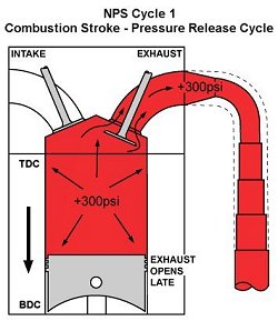
NPS Cycle 1 Combustion Stroke ? Pressure Release Cycle
|
After combustion about 300psi of high pressure gas remains in the cylinder of a typical V8 engine before the exhaust valve opens. The Negative Pressure Supercharging process uses this high pressure gas to REDUCE the pressure (increase the vacuum) in the cylinder and pull a larger intake charge into the engine.
As the exhaust valve opens, the high pressure gas from combustion forces itself through the small and short pipes of the NPS Tri-Y header at 600 ft/sec. This is twice the gas speed of the large pipe headers used by standard and race engines shown by the broken lines.
The high velocity gas produces a much higher vacuum in the small pipe header which pulls the exhaust gases out of the engine and REDUCES the pressure (increases the vacuum) in the cylinder.
However, the high pressure gas will remain compressed in a small pipe for only a short distance before it builds up backpressure and restricts the gas flow.
|
Therefore, the small pipes of the NPS Tri-Y header are very short and connect to a megaphone pipe. This allows the compressed gas in the small pipe to gradually expand into the larger section of the megaphone pipe at a high velocity BEFORE it builds up backpressure and restricts the gas flow. For more details see NPS Tri-Y Headers
NOTE
Lower pressure (higher vacuum) is produced behind all moving objects that travel at a high speed
Therefore, the faster the speed of a moving object, the lower the pressure (higher the vacuum) is behind the object. The same principle applies to the gas flow in the primary pipe of a typical header. The smaller the pipe, the faster the gas speed and therefore the lower the pressure (higher the vacuum) is behind the gas flow in the header. However, this only works if the small pipe is short and made shorter the smaller the pipe.
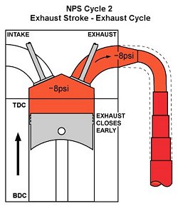
NPS Cycle 2 Exhaust Stroke ? Exhaust Cycle
|
At the end of the exhaust stroke, the lower pressure (higher vacuum) produced by the NPS Tri-Y header is trapped in the combustion chamber during the overlap period by...
|
•
|
Closing the exhaust valve 12° earlier before TDC
|
|
•
|
Using 10° less overlap duration
|
|
•
|
Using .150" less exhaust valve lift
|
|
•
|
Synchronising the above 3 valve timing events
|
The lower pressure (higher vacuum) in the cylinder also helps pull the piston towards TDC during the exhaust stroke which reduces the engines pumping work.
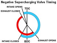
However, the above 3 valve timing events are part of a more complex valve timing process that requires synchronising 8 valve timing events and optimising them to within 1° duration and .010" lift in order to...
|
|
•
|
Trap the lower pressure (higher vacuum) in the cylinder at the end of the exhaust stroke by closing the exhaust valve early and using less overlap duration and exhaust valve lift
|
|
•
|
Move the lower pressure (higher vacuum) to the intake stroke during the overlap period by synchronising the exhaust valve closing, overlap duration and exhaust valve lift events
|
|
•
|
Trap the larger intake charge pulled into the cylinder during the early part of the intake stroke by closing the intake valve early
|
|
•
|
Prevent the lower pressure (higher vacuum) from pulling the intake charge into the exhaust system during the overlap period
|
For more details see NPS Valve Timing
|
|
NOTE
The above 3 valve timing events are examples only. They are not the optimum valve timing events for each different size engine which is proprietary information.
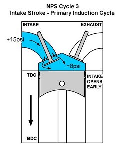
NPS Cycle 3 Intake Stroke ? Primary Induction Cycle
|
At the beginning of the intake stroke, the intake valve opens 5-10° earlier before TDC. This allows the lower pressure (higher vacuum) trapped in the combustion chamber during the overlap period to pull the intake charge into the cylinder BEFORE the piston begins the intake stroke.
As a result the intake charge rapidly fills the cylinder during the EARLY part of the intake stroke.
Therefore, the lower the pressure (higher the vacuum) that is trapped in the combustion chamber during the overlap period, the larger intake charge the Negative Pressure Supercharging process pulls into the cylinder during the early part of the intake stroke.
NOTE
The above valve timing event is an example only. It is not the optimum valve timing event for each different size engine which is proprietary information.
|
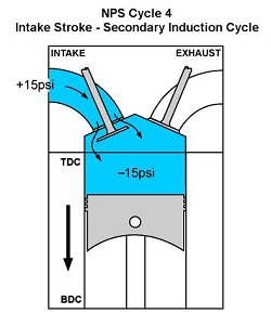
NPS Cycle 4 Intake Stroke ? Secondary Induction Cycle
|
As the piston moves down the cylinder during the intake stroke, it further reduces the pressure (increases the vacuum) in the cylinder in addition to the lower pressure (higher vacuum) trapped in the combustion chamber during the overlap period.
As a result the much greater pressure differential between the higher atmospheric pressure outside the engine and the much lower pressure (higher vacuum) in the cylinder...
|
•
|
Pulls a larger intake charge into the cylinder at a higher velocity during the EARLY part of the intake stroke
|
|
•
|
Produces violent air turbulence with NO restriction to air flow
|
|
•
|
Creates a homogenous intake charge that burns faster and cleaner
|
|
•
|
Allows large intake ports and valves with high lift to flow a larger volume of air into the cylinder from 1000-4500 rpm than small intake ports and valves with low or high lift
|
|
NOTE
Negative pressure below zero shown in the NPS Cycle 4 diagram is used only as an example to demonstrate the force of a vacuum
While it?s understood that negative pressure (vacuum) can not be reduced below zero, the force of a vacuum (which is measured in air molecules per cc instead of psi) is not understood as well as the force produced by psi of positive pressure. Therefore, -15psi of negative pressure below zero is used only as an example to demonstrate that whether the same pressure differential is below or above 15psi at sea level it produces the SAME force. For more details see Negative pressure produces the SAME force as positive pressure
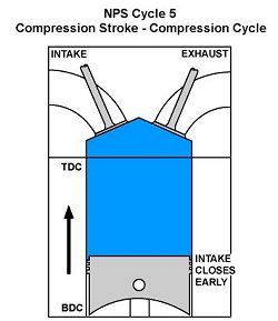
NPS Cycle 5 Compression Stroke ? Compression Cycle
|
At the end of the intake stroke, the intake valve closes 10? earlier after BDC to...
|
•
|
Trap the larger intake charge pulled in the cylinder during the EARLY part of the intake stroke
|
|
•
|
Prevent the larger intake charge from being forced back into the intake manifold during the compression stroke
|
The lower pressure (higher vacuum) trapped in the combustion chamber during the overlap period causes the intake charge to rapidly fill the cylinder during the EARLY part of the intake stroke. This pulls a larger intake charge into the cylinder from 1000-4500 rpm but requires the intake valve to close much earlier in order to trap the larger intake charge in the cylinder.
NOTE
The above valve timing event is an example only. It is not the optimum valve timing event for each different size engine which is proprietary information.
|
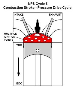
NPS Cycle 6 Combustion Stroke ? Pressure Drive Cycle
|
At the beginning of the combustion stroke the larger homogenous intake charge produces substantially more combustion pressure and a faster burn from 1000-4500 rpm than standard or race engines.
This allows Negative Pressure Supercharging to produce a lot more torque and horsepower over a broader rpm range.
However, the larger intake charge is more difficult to ignite the colder the air induction temperature BELOW 40°C (104°F).
Therefore, Negative Pressure Supercharging uses...
|
•
|
Hot Air Induction to increase the speed of combustion to just BEFORE the point of self ignition in order to increase combustion pressure
|
|
•
|
Cold Cooling System to maintain the optimum combustion temperature and burn rate in order to increase combustion pressure and prevent the hotter and faster burn from igniting prematurely
|
|
•
|
Special Ignition Timing to prevent the hotter and faster burn from igniting prematurely
|
|
•
|
Low compression and open chamber heads to prevent the hotter and faster burn from igniting prematurely
|
|
By using Hot Air Induction with the Negative Pressure Supercharging process it produces Homogenous Thermal Charge Spark Ignition (HTCSI) combustion. This produces a much faster and cleaner burn and more combustion pressure than cold air induction. The Cold Cooling System and Special Ignition Timing maintain the optimum burn rate of HTCSI combustion.
As a result Negative Pressure Supercharging and HTCSI combustion produce a lot more torque, fuel efficiency and a cleaner burn than standard engines that use cold air induction, hot cooling systems and more ignition timing. For more details see Ultra Fast Burn
Hot Air Induction is also produced by supercharger and turbocharger air pumps The NPS process has the opposite problem...it reduces the air induction temperature which makes the larger intake charge too cold and difficult to ignite. Therefore, heat is drawn from the exhaust headers to increase the temperature of the intake charge to the optimum burn rate. This produces an intake charge that is hotter than outside temperatures which allows the larger intake charge to burn faster and produce more power. However, because the NPS process uses a Cold Cooling System instead of an intercooler it allows using an even hotter intake charge which produces a further increase in power.
Therefore, Hot Air Induction is needed to ignite the larger intake charge produced by supercharging whether the heat is generated by supercharger air pumps or drawn from the exhaust headers by the NPS process.
NPS process uses a Cold Cooling System instead of an intercooler
The NPS Cold Cooling System prevents combustion from exceeding the optimum temperature and burn rate with the hotter and faster burn produced by Hot Air Induction. This prevents pre-ignition and allows the engine to produce more power the hotter the air induction temperature ABOVE 40°C (104°F) but ONLY if the water temperature is kept between 40-50°C (104-122°F). Because cold water is able to draw more heat from the hotter and faster burn produced by hot air induction than hot water, the cold water prevents the combustion chamber from running too hot and igniting the intake charge prematurely. Therefore, cold water is a lot more effective than hot water at maintaining the optimum combustion temperature and burn rate with the hotter intake charge. This allows the engine to run HOT with cold water and hot air induction...ONLY the water passages run cold.
Therefore, supercharger and turbocharger air pumps can also use the NPS Cold Cooling System and Ignition Timing to produce more power with Hot Air Induction than with intercoolers.
|